Data output panel 2
Layers
Layer Manager

The gallery has already been analysed in the basic section of this work where the ascending passage line was placed into the groove in the gallery side wall and an approximate value for the angle of the floor was determined. This basic analysis showed that the length of the walls overlaps in cubits was related to the angle of the overlap in radians by a factor of 200.
The south end of the gallery is the easier of the two ends to understand and teaches the system that is also used on the north wall. If you click here you can see the south end wall in more detail, and of particular note are the following points
Each of the overlaps was measured to be one seventh of a cubit in horizontal length and the south wall has been specifically designed so that all of these overlaps form a logical, repetitive system which can be seen by clicking here.
The additional length measured along the slope of the side walls that needs to be added as you descend from one overlap to the next is 1/7*cos(a), where a is the angle of the lower of the two overlaps. Because of the cosine term, the angle and length are co-dependent, and the calculation is iterative. From analysis it converges to an accuracy of 12 significant figures after 5 iterations.
Because the overlaps of the south wall are repetitive, any small discrepancy from the consistent pattern of 1/7 cubit horizontal overlaps must be due to movement in the stones that has been caused by Earthquakes since the time that the building was constructed. If you display the surveying measurements of the verticality of the wall ends as documented by Petrie, where the measurements are displayed in inches, you can see the distance that the bottom of each overlap is offset vertically compared to the top of the same overlap.
You can see that there are small movements that have occurred in the 2nd, 3rd and 6th overlaps of 0.1" shown in white. But on the lowest and on the 1st overlap there are much larger offset distances of 0.45" and 0.20" shown in yellow which are not due to stone movement. The reason that these measurements are significant is that the three values are the lengths of the three sides of the triangle that was shown on the previous page (page D5). The illustration below shows Petrie's original notes for these lower parts of the wall, and right of the illustration is the triangle in question.
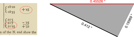
If you zoom in to show the lower section of the south wall in detail, the overlaid drawing shows the non-vertical nature of these overlaps with the vertical angle exaggerated for clarity and the exact values of the three offsets shown in yellow. These offsets cannot be measured to the accuracy in the illustration and are therefore deliberate theoretical values which are known with absolute precision.
Because of the method by which the gallery end wall mathematics works with each wall overlap calculation being dependent upon the previous overlap calculations it is imperative to ensure that the two very similar lengthed sides of the triangle are placed in the correct order as shown on the diagram with the 0.45526" offset appearing at the top and the 0.41207" offset at the floor level. To disambiguate these two lengths the architects have ensured that the stone work of the antechamber entrance door area reflects the ratios of these two lengths in the architecture as shown on the following photographic illustration.
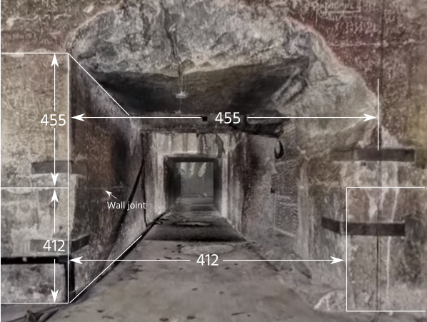
The wall stones of the start of the antechamber passage are built in a 455:412 ratio, as is the width of the doorway with the 'damaged' section of the door surreptitiously concealing the width ratio.
The full system of overlaps for the south wall can be seen on the following illustration.
So that all of these measurements of the wall overlaps can be cross checked and verified, the architects have included an anti-earthquake checking feature at the foot of the wall, which is labelled on the drawing. These are two rectangular holes cut out on either side of the gallery and which are of different lengths.
That on the west side is 20.6" (1 cubit) in length which is the total of the lengths of all of the horizontal overlaps. The length of the hole on the east side is the maximum width of the south wall which includes both the horizontal overlap total plus the offsets due to the non-vertical lower walls. The length of this hole is therefore 20.6" + 0.45526" + 0.19369, giving a total length of 21.249", and which was was surveyed as 21.2".