
Data output panel 2
Layers
Layer Manager

As explained earlier (page C8), the moving base line of the secondary ellipse has to be formed from the south (left) end of that ellipse's equator line, and the first of the pyramid's architectural features that indicates that that is the correct way of forming the geometry was the "well shaft's" construction.
The second way of knowing that the formation geometry is correct is by looking at what happens if you create the geometry incorrectly and use the north end of the secondary ellipse's equator line, as shown on the interactive drawing. Due to the asymmetric nature of the tangent line that is forming the lower northern shaft, the hexagonal rod changes position in the shaft when the geometry is badly formed. Click here to zoom in on the intersect area.
The change in the geometry is subtle. The straight section of the hexagonal rod plot is no longer parallel to the floor of the shaft
The photographs from the robotics engineering team's website are shown again below.
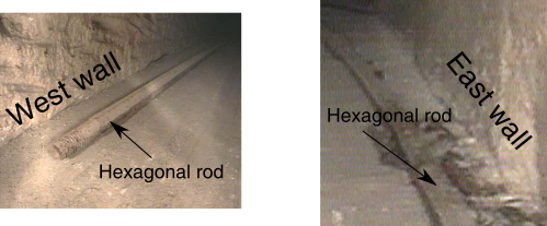
Notice how the straight section of the hexagonal rod starts on the left side of the shaft (first photo) when viewed from above and at the bend point in the shaft it is on right side (second photo). The reason for the rod being positioned in this way is so that you can determine when you have the geometry incorrectly formed.
When the hexagonal rod starts at the left side of the shaft and ends at the right side of the shaft, you MUST be viewing the shaft vertically from above. On the interactive drawing you can see that the rod starts on the left of the shaft and at its bend point it is on the right of the shaft, meaning that the geometry that is forming this drawing cannot be correct.
The pyramid and all of the geometry is being viewed 'horizontally' from the east, and therefore the hexagonal rod should be parallel with and touching the floor of the shaft. This subtle detail, along with the triangular structure in the 'well shaft' confirms that the dynamic geometry that is being used is to draw the rod on the previous page (page C10) is being correctly formed.