Data output panel 2
Layers
Layer Manager

To understand the construction of the gallery it is necessary to start in the same manner as was done on the previous two pages, with the drawing showing the principal ellipse's unrotated polar cross section and the ascending passage highlighted in green and showing its unrotated geometric angle of 26° 1' 34.01".
If you zoom in on the gallery area you can see that the surveyed floor of the gallery on the drawing is at a steeper angle than that of the geometric ascending passage line that is formed from the unrotated ellipse. Petrie surveyed the gallery's floor angle as being 26° 16' 40", which is also a considerably larger angle than the ascending passage line after the rotation is applied to the ellipse as shown on the previous page (page B7). For clarity the lines in question have the following angles:
On the drawing you can see a grey line running along the length of the gallery half way up the gallery wall, and this is an 8cm deep groove that is cut out of the stonework along the length of the gallery.
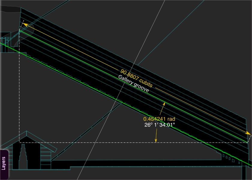
If the ascending passage line of the unrotated Earth is placed into the groove that runs down the gallery wall and the units used to display information are selected as being the architects known unit of linear measure, the cubit (0.523 m) , and radians for angular measure then the following drawing shows the result. On the drawing the angle of the geometric line of the ascending passage that has been placed in the groove is shown in radian angular measurement as 0.454241 rad, and the surveyed length of the groove is displayed in cubits as 90.8807 cubits.
The length of the groove in cubits is 200 times the ascending passage angle of the unrotated Earth, in radians.
If you click here (click and hold) you can see the overlaps of stonework that make up the south end wall of the gallery. The side walls of the gallery get longer as you descend from the groove to the floor, and get shorter as you vertically ascend. These horizontal length difference were surveyed as being 1/7th of a cubit between each overlap. A very similar situation occurs on the north end wall meaning that each of the gallery side wall overlaps is 2/7th of a cubit longer than the previous as you go down the levels.
If, from the analysis above the length of each side overlap of the gallery has to be 200 times its radian angle, and the because the lengths of each side overlap are known, then the angles of each side overlap can be calculated, and thereby the floor angle of the gallery.
By this system the floor of the gallery lust be 6/7 of a cubit, or 0.857142 cubits longer than the groove, and therefore its angle must be 0.857142 / 200 radians larger than the groove angle. Click here to display the floor geometry drawing and you can see that the floor angle when determined in this manner is 26° 16' 18.01" compared to the surveyed angle of 26° 16' 40"
This construction system identified in the gallery is correct, but these basic calculations will be substantially refined when the overall architecture system is calibrated later in this work.
For now, it is sufficient to leave the gallery with the knowledge that length (cubit) = 200 * angle (rad) and that the architects of this building are using radian angular measurements.